 Microcontrollers & architecture
 3 min read
The clock system
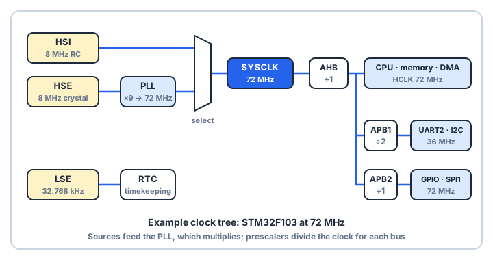
Everything in a microcontroller happens on a clock edge. The clock system picks a source, either an internal oscillator or an external crystal, multiplies it with a PLL, then divides it with prescalers so each bus and peripheral gets the frequency it needs.
Pick a source
- Internal RC oscillator (HSI on STM32): starts instantly and needs no extra parts, but is only accurate to about 1% at room temperature, and less across temperature.
- External crystal (HSE): accurate to tens of parts per million, which USB and CAN need. It takes a few milliseconds to start.
- 32.768 kHz crystal (LSE): 215 Hz, so a 15-bit counter overflows exactly once a second. That is why it drives the real-time clock.
An STM32F103 always starts on the HSI after reset. Startup code then switches to the crystal and the PLL.
Multiply, then divide
A phase-locked loop (PLL) multiplies a stable reference up to a high frequency: 8 MHz × 9 = 72 MHz, the F103's maximum. Prescalers then divide that clock for each bus. On the F103, the APB1 bus is limited to 36 MHz, so it runs at ÷2.
| Clock | Derived from | Frequency | Feeds |
|---|---|---|---|
| SYSCLK | HSE × 9 (PLL) | 72 MHz | The whole tree |
| HCLK | AHB ÷ 1 | 72 MHz | CPU, memory, DMA |
| PCLK1 | APB1 ÷ 2 | 36 MHz | USART2, I2C, TIM2–4 |
| PCLK2 | APB2 ÷ 1 | 72 MHz | GPIO, SPI1, USART1, ADC |
Three gotchas
- Flash wait states: Flash cannot keep up with a fast CPU. The F103 needs 2 wait states above 48 MHz. Raise the clock first and the CPU reads garbage.
- Timer doubling: when an APB prescaler is not ÷1, the timers on that bus run at twice its clock, so TIM2 still ticks at 72 MHz.
- Clock gating: every peripheral's clock is off after reset to save power. Nothing works until you set its enable bit in the RCC.